
Typical equipment
Identify the circuit served by the pump: the machine may have separate drives for its main and auxiliary functions.
What the hydraulic system does
Depending on the machine design, hydraulic actuators can support clamping, injection or auxiliary movement. The pump supplies the circuit; valves and controls determine how the machine uses the flow.
Illustrative sequence only; the actual machine cycle and control system may differ.
Pump selection checks
Clamping, injection and auxiliary motion · Flow and pressure change through the molding cycle
Which movement needs the flow?
List the flow and pressure needed for mold approach, injection, holding and auxiliary movements.
What happens during holding?
Include holding time and explain how the circuit maintains pressure during that stage.
Is the drive speed controlled?
For servo drives, send the motor and drive specifications, operating speed range and starting conditions.
- Describe how flow and load change through the machine cycle.
- Identify fixed-speed or variable-speed drive requirements.
- Include noise expectations, operating hours and available cooling.
Check the required operating points against the pump document, then compare the shaft, mounting, rotation and ports.
MACHINE DUTY
Specify each stage of the molding cycle
| Stage | Information to collect | Why it matters |
|---|---|---|
| Approach and movement | Required actuator speed and simultaneous movements | Record the flow demand and available shaft speed. |
| Injection or pressing | Required force, pressure rise and duration | Separate the loaded working point from fast travel. |
| Holding and return | Holding time, unloading arrangement and cooling | Describe the control strategy and how demand changes through the cycle. |
Include the machine cycle or hydraulic schematic, drive and controls, oil, available space and noise requirements. For variable-speed operation, check the pump’s speed range and starting limits.
Check the series documents
Find T6 / T7, V / VQ, SQP documents in the catalog, then check the model and configuration against your machine requirements.
Compare the product details
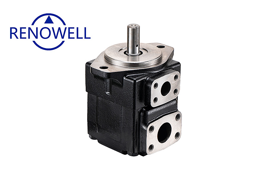
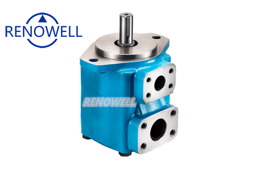
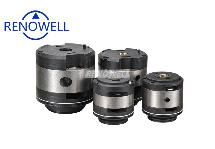
Use the catalog photos to identify the series, then open its drawings and technical data. Final selection depends on the machine specification.
Send your machine requirements
Supply the machine function, flow and pressure requirements, drive details and expected cycle. For servo systems, clarify which motor, drive and control components are included in the project.
Include the required quantity, destination and delivery expectations. For a replacement, add the old pump’s nameplate and photographs of the installation.
Discuss your application ›These guides describe typical circuits. They are not customer case studies or equipment approvals.