
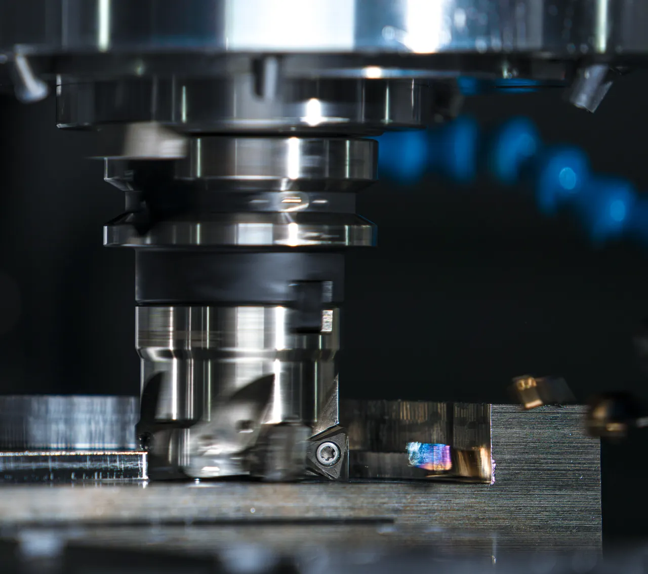
Typical equipment
Identify the circuit served by the pump: the machine may have separate drives for its main and auxiliary functions.
What the hydraulic system does
A pump feeds the hydraulic circuit that powers the actuator. The workpiece, tooling and machine structure determine the force and motion requirements; the pump alone does not determine the accuracy of the process.
Illustrative sequence only; the actual machine cycle and control system may differ.
Pump selection checks
Workholding, pressing and auxiliary actuation · Position, clamp, hold and release
Workholding or machining power?
State which function the pump supplies. Spindle motor power does not specify the hydraulic pump requirement.
How often does the circuit operate?
Record cycles per hour, holding time and any actuators that run together.
What must fit the existing power unit?
Send the mounting, shaft and port details, plus the available space. For an existing unit, note oil temperature and any unusual noise.
- Distinguish movement demand from pressure-holding demand.
- State the available installation space and mounting details.
- Provide operating hours and any machine-specific noise requirements.
Check the required operating points against the pump document, then compare the shaft, mounting, rotation and ports.
MACHINE DUTY
Separate positioning, clamping and release
| Stage | Information to collect | Why it matters |
|---|---|---|
| Position | Travel time and actuator dimensions | Identify the flow needed while the actuator is moving. |
| Clamp or press | Required force, working pressure and holding duration | State the loaded duty and how the circuit maintains pressure. |
| Release and reset | Return movement and cycle frequency | Include return timing, simultaneous functions and thermal conditions. |
Include the machine function, drive speed, installation drawing and hydraulic schematic. Precision and safe holding depend on the whole machine and its controls.
Check the series documents
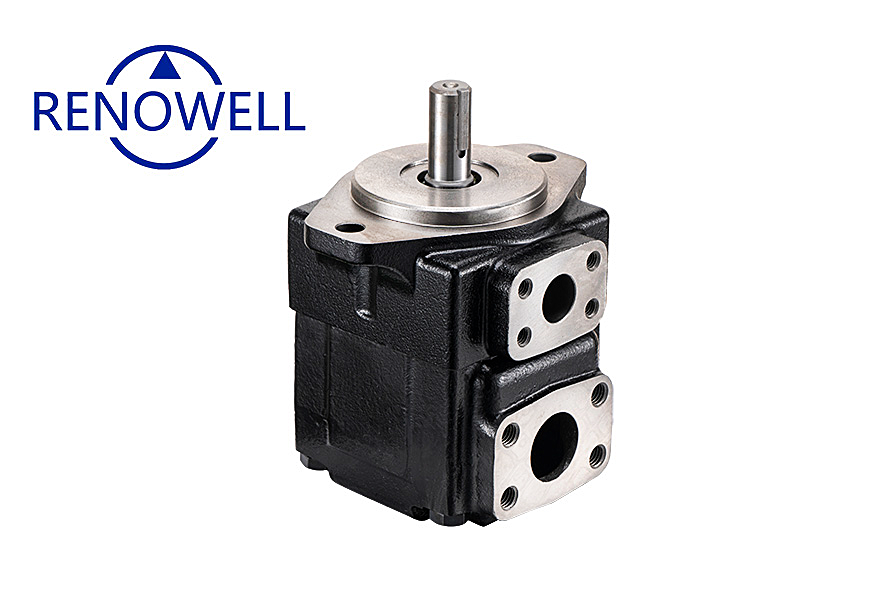
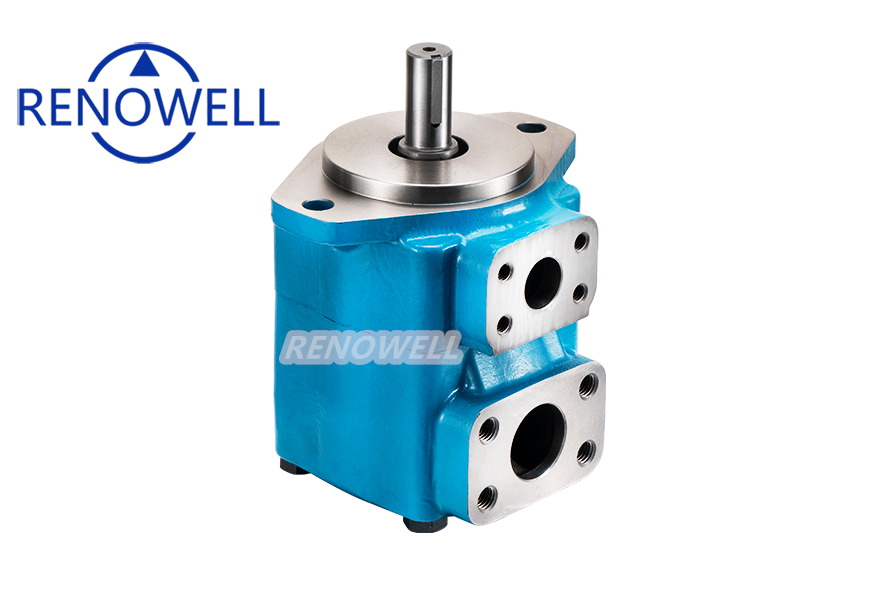
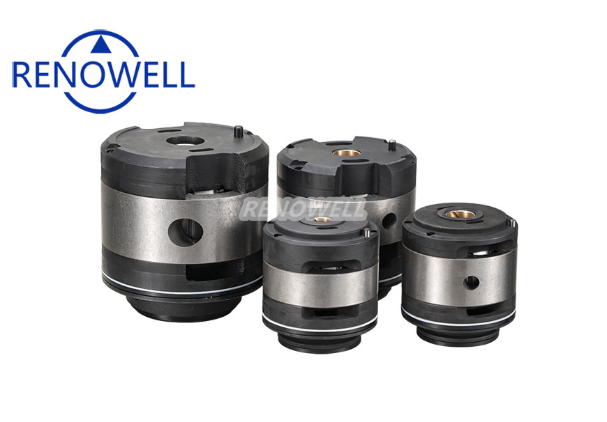
Find T6 / T7, V / VQ, SQP documents in the catalog, then check the model and configuration against your machine requirements.
Compare the product details
Use the catalog photos to identify the series, then open its drawings and technical data. Final selection depends on the machine specification.
Send your machine requirements
Include the hydraulic schematic if available, actuator requirements and existing pump code. For a new installation, ask the machine designer to confirm the required operating points.
Include the required quantity, destination and delivery expectations. For a replacement, add the old pump’s nameplate and photographs of the installation.
Discuss your application ›These guides describe typical circuits. They are not customer case studies or equipment approvals.